Circuit breakers using only one type of protection often fail to effectively manage both safety and continuous power supply. For instance, small current overloads might trigger false trips that interrupt processes, while delayed reactions to major short circuits could escalate into dangerous situations. This article explores two key technologies three stage protection, and tripping characteristic curves to help readers understand how a scientifically configured circuit breaker ensures precise fault protection.
What Is Three Stage Protection in Circuit Breakers?
In industrial and residential electrical systems, the severity of circuit faults varies significantly. For instance, a household oven operating for extended periods may cause a continuous overload of 1.2 times the rated current, whereas an electric motor startup can generate an instantaneous inrush current exceeding 10 times the rated value. Traditional single stage breakers struggle to distinguish between fault types, either tripping too frequently or responding too slowly, compromising safety. Three stage protection technology, through a graded response mechanism, enables millisecond level fault identification and processing.
Three stage protection includes long time overload protection (L), short time short circuit protection (S), and instantaneous short circuit protection (I), collectively known as LSI protection. When ground fault protection (G) is added, it becomes LSIG four stage protection.
– Long time overload protection: Operates with a longer delay to tolerate certain overload levels (e.g., 1.05 to 5 times the rated current), preventing unnecessary shutdowns while protecting equipment from overheating.
– Short time short circuit protection: When current surges (e.g., 5 to 10 times the rated current), an electronic trip unit introduces a brief delay (0.1–0.4 seconds) to allow downstream breakers to trip first, preventing unnecessary upstream power cuts.
– Instantaneous short circuit protection: The fastest response mode, instantly cutting off extreme overcurrent conditions (e.g., 10–20 times the rated current) to restore normal circuit operation quickly.
Three stage protection defines the overcurrent protection characteristics of a circuit breaker.
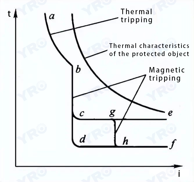
To maximize the utilization of electrical equipment while minimizing the impact of faults, circuit breaker protection must be selective. The characteristic curve of a circuit breaker can be divided into three sections:
- Section AB: overload protection section:
The magnitude of the operating current is inversely proportional to the duration of the operating time.
- section DF: instantaneous action section:
When the fault current exceeds the predefined D point threshold, the overcurrent tripper immediately triggers circuit isolation.
- CE section: timedelayed action section:
When the current exceeds the point C threshold, the overcurrent tripper will act after a certain delay time to remove the faulted circuit.
 What Are Circuit Breaker Tripping Characteristic Curves?
 What Are Circuit Breaker Tripping Characteristic Curves?
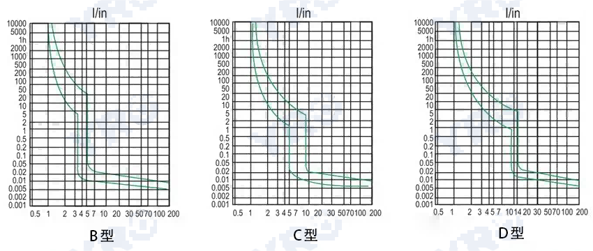
The main types are A, B, C, D, and K, each suited for specific applications:
– A curve: Tripping current (2–3)In, used for semiconductor circuit protection.
– B curve: Tripping current (3–5)In, suitable for residential appliances and household distribution.
– C curve: Tripping current (5–10)In, ideal for lighting circuits and distribution systems with moderate inrush currents.
– D curve: Tripping current (10–20)In, designed for high inrush current loads like transformers, solenoids, and motors.
– (5) K curve: with 1.2 times the thermal release action current and 8~14 times the magnetic release action range, suitable for the protection of motor line equipment, high resistance to inrush current capacity.
In practical applications, B, C, and D curve circuit breakers are the most commonly used. Different manufacturers may offer slight variations in these curves.
 Differences Between A, B, C, D, and K Tripping Curves
 Differences Between A, B, C, D, and K Tripping Curves
- Acurve: Shortcircuit trip threshold of 2–3 In, used for electronic and communication equipment protection.
- Bcurve: Shortcircuit trip threshold of 3–5 In, used for generator load protection.
- Ccurve: Shortcircuit trip threshold of 5–10 In, commonly used in lighting distribution.
- Dcurve: Shortcircuit trip threshold of 10–20 In, used for motor circuits and large inductive loads. Many manufacturers limit this to 10–14 In for practicality.
- Kcurve: Shortcircuit trip threshold of 8–15 In, ideal for motor protection. Unlike other curves, the K curve has a thermal non tripping current of 1.05 In and a tripping current of 1.2 In, making it particularly suitable for motor overload protection.
For motor protection using D curve breakers, an additional thermal relay is required for overload protection.
Conclusion
This article has examined circuit breakers from two perspectives: three stage protection and tripping characteristic curves. Through a graded response mechanism and precise curve matching, it is possible to enhance system safety while reducing unnecessary tripping. Properly configuring circuit breakers not only lowers maintenance costs but also strengthens electrical safety.