Circuit breakers using only one type of protection often fail to effectively manage both safety and continuous power supply. For instance, small current overloads might trigger false trips that interrupt processes, while delayed reactions to major short circuits could escalate into dangerous situations. This article explores two key technologies three stage protection, and tripping characteristic curves to help readers understand how a scientifically configured circuit breaker ensures precise fault protection.
What Is Three Stage Protection in Circuit Breakers?
In industrial and residential electrical systems, the severity of circuit faults varies significantly. For instance, a household oven operating for extended periods may cause a continuous overload of 1.2 times the rated current, whereas an electric motor startup can generate an instantaneous inrush current exceeding 10 times the rated value. Traditional single stage breakers struggle to distinguish between fault types, either tripping too frequently or responding too slowly, compromising safety. Three stage protection technology, through a graded response mechanism, enables millisecond level fault identification and processing.
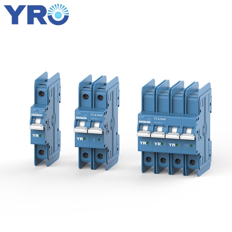
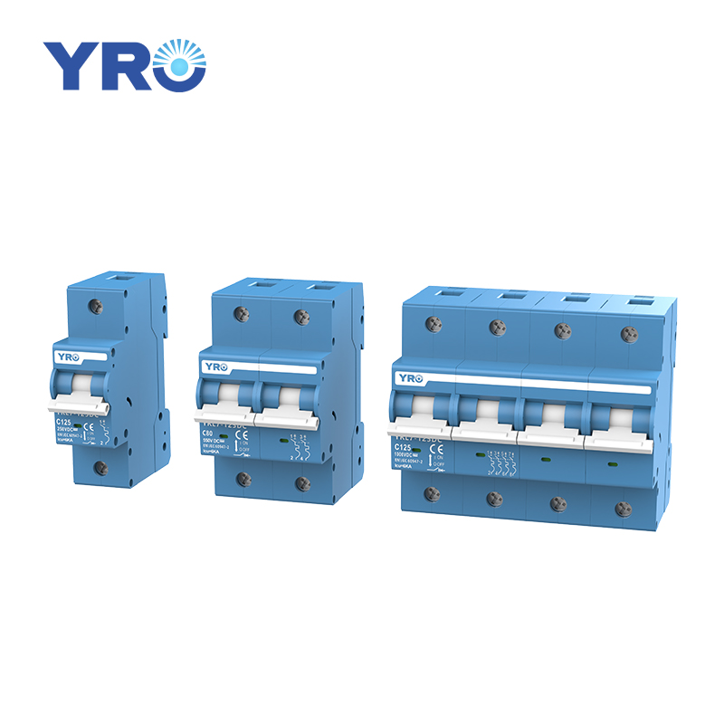
Three stage protection includes long time overload protection (L), short time short circuit protection (S), and instantaneous short circuit protection (I), collectively known as LSI protection. When ground fault protection (G) is added, it becomes LSIG four stage protection.
– Long time overload protection: Operates with a longer delay to tolerate certain overload levels (e.g., 1.05 to 5 times the rated current), preventing unnecessary shutdowns while protecting equipment from overheating.
– Short time short circuit protection: When current surges (e.g., 5 to 10 times the rated current), an electronic trip unit introduces a brief delay (0.1–0.4 seconds) to allow downstream breakers to trip first, preventing unnecessary upstream power cuts.
– Instantaneous short circuit protection: The fastest response mode, instantly cutting off extreme overcurrent conditions (e.g., 10–20 times the rated current) to restore normal circuit operation quickly.
Three stage protection defines the overcurrent protection characteristics of a قاطع الدائرة.
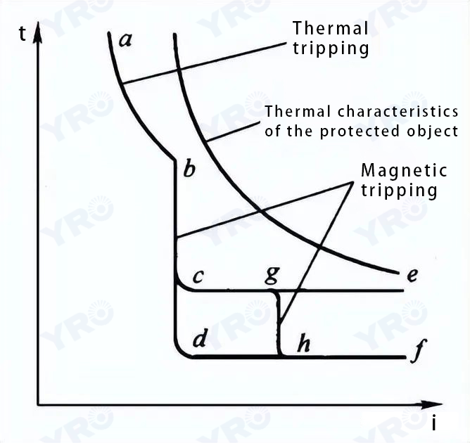
To maximize the utilization of electrical equipment while minimizing the impact of faults, circuit breaker protection must be selective. The characteristic curve of a circuit breaker can be divided into three sections:
- Section AB: overload protection section:
The magnitude of the operating current is inversely proportional to the duration of the operating time.
- section DF: instantaneous action section:
عندما يتجاوز تيار الخطأ العتبة المحددة مسبقًا لنقطة D، يقوم جهاز الفصل الزائد بتفعيل عزل الدائرة على الفور.
- قسم CE: قسم الزمن المؤجل للعمل:
عندما يتجاوز التيار عتبة النقطة C، سيعمل جهاز الفصل الزائد بعد فترة زمنية معينة لإزالة الدائرة المخطئة.
 ما هي خصائص منحنيات فصل قواطع الدائرة؟
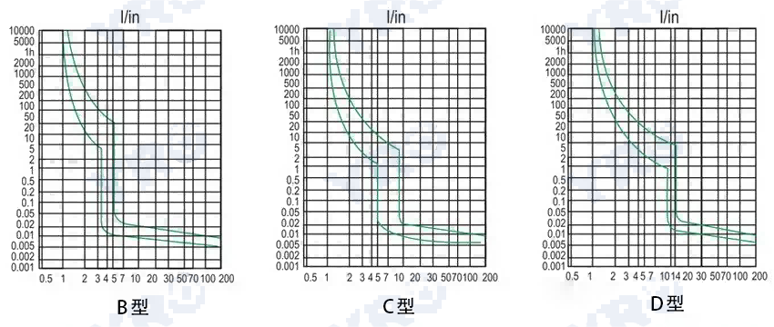
الأنواع الرئيسية هي A وB وC وD وK، كلٌ منها مناسب لتطبيقات محددة:
– منحنى A: تيار الفصل (2-3)In، يُستخدم لحماية الدوائر شبه الموصلة.
– منحنى B: تيار الفصل (3-5)In، مناسب للأجهزة السكنية والتوزيع المنزلي.
– منحنى C: تيار الفصل (5-10)In، مثالي لدوائر الإضاءة وأنظمة التوزيع ذات التيارات العالية المتوسطة.
– منحنى D: تيار الفصل (10-20)In، مصمم للأحمال ذات التيار المرتفع مثل المحولات والصمامات والمحركات.
– منحنى K (5): مع 1.2 مرة من تيار فعل الإفراج الحراري و8~14 مرة من نطاق فعل الإفراج المغناطيسي، مناسب لحماية معدات خط المحرك، وتكون مقاومة عالية لتيار الاندفاع.
في التطبيقات العملية،, تُعتبر قواطع الدائرة من المنحنيات B وC وD الأكثر استخداماً. قد تقدم الشركات المصنعة اختلافات طفيفة في هذه المنحنيات.
 الاختلافات بين منحنيات الفصل A وB وC وD وK
- منحنى A: عتبة فصل الدائرة القصيرة من 2-3 In، يُستخدم لحماية المعدات الإلكترونية والاتصالات.
- منحنى B: عتبة فصل الدائرة القصيرة من 3-5 In، يُستخدم لحماية أحمال المولد.
- منحنى C: عتبة فصل الدائرة القصيرة من 5-10 In، يُستخدم عادةً في توزيع الإضاءة.
- منحنى D: عتبة فصل الدائرة القصيرة من 10-20 In، يُستخدم لدارات المحرك والأحمال الحثية الكبيرة. يحدد العديد من الشركات المصنعة هذا إلى 10-14 In للجدوى.
- منحنى K: عتبة فصل الدائرة القصيرة من 8-15 In، مثالي لحماية المحرك. على عكس المنحنيات الأخرى، يحتوي منحنى K على تيار عدم الفصل الحراري بمقدار 1.05 In وتيار الفصل بمقدار 1.2 In، مما يجعله مناسبًا بشكل خاص لحماية الحمل الزائد للمحرك.
لحماية المحرك باستخدام قواطع منحنى D، يلزم وجود مرحل حراري إضافي لحماية الحمل الزائد.
Conclusion
لقد تناولت هذه المقالة قواطع الدائرة من منظورين: حماية من ثلاث مراحل وخصائص انقطاع التيار. من خلال آلية استجابة متدرجة ومطابقة دقيقة للمنحنيات، من الممكن تعزيز سلامة النظام مع تقليل الانقطاعات غير الضرورية. إن التكوين الصحيح لقواطع الدائرة لا يقلل فقط من تكاليف الصيانة ولكنه يعزز أيضًا السلامة الكهربائية.